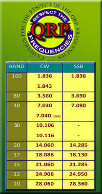
Here is my first attempt at an article. I wanted to make a all band antenna without the long tail of a G5RV. I did some research and remembered that awhile back I had received an antenna from a fellow ham that had been struck by lightning. It was a 40 meter Carolina windom.
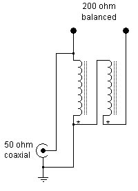
Started by taking the 2 baluns apart to see what they were made of. Found the upper one was a 4:1 to 1 balun. It had 15 turns around a 3/8 ferrite rod.
Mine was burnt and broken from the lightning hit.
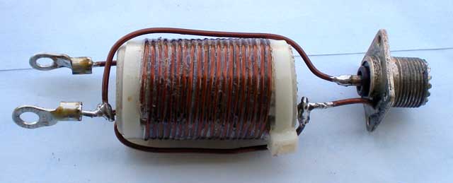
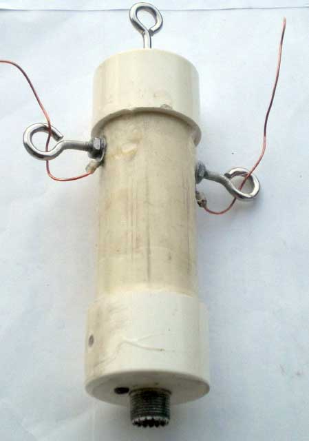
Searched on the internet how to make one (new they are approx. $20-$30). I wound 10 turns of the 14 gauge wire on a small piece of 1 inch O.D. PVC pipe. This was then enclosed in a small piece of 1 1/2 inch O.D. PVC pipe and end caps for weatherproofing. Two stainless steel eye-bolts are used to attach the antenna wires and another to support the balun.
(photos were taken from the internet)
Buying one probably would have been easier but there is no experience in that.
Next was to take apart the other balun and see what made it tick. There was no damage to this one just a rattle (curiosity killed the cat). This one was a 1:1 Choke balun to dissipate RF. Took it apart and found the ferrite rod hand broken. Guess I need to make another. Back to the internet.
Here is what I found I needed a choke balun to keep RF from getting back into my radio and finding new ways to make sure I stayed awake late at night. I found instructions online for a simple and cheap coax 1:1 choke balun. It is supposed to handle 160 meters to 10 meters which is perfect for my application. I made some modifications to the construction but I kept the critical parts intact. Mainly I added HF connectors at each end so that it can go inline in with my coax to the antenna. I figure I can also use it later for other antennas because I can simply make an adapter that screws onto one end to allow me to hookup wires directly to it for either ladder line or antenna wires. It’s a bit heavy so it’d have to be supported by some rope instead of just the wire if I needed to have it up in the air, but that isn’t a big deal really.
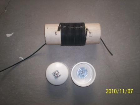
Here are the beginning parts of the 1:1 coax choke balun. I have about 21 feet of RG-58u wrapped around a 3″ PVC pipe form that I drilled two holes in to feed the coax into the inside of the pipe. At the bottom you can see the end caps with the SO-239′s installed already. I bolted them in with 6-32 screws with a nice large fender washer to provide a strong backing and to spread the stress out across the cap so that if it has anything hanging on either end it will not break the cap and pull out. Everything is sealed up with some really nice 35 year, silicone impregnated, permanently flexible clear caulking to provide a weather proof seal that should last a long time. I also tacked down the winding in place using a few beads of the same caulking to keep everything nice and tight.
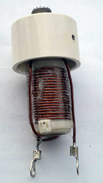
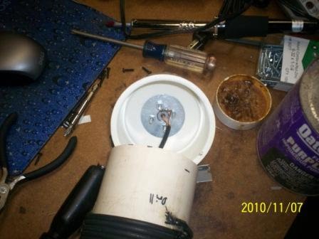
Here is a close-up shot of the two end caps where you can more clearly see the method I used for mounting the SO-239 connectors. With the fender washer as a backer it would take quite a bit of force to pull the connector out. Odds are the coax will pull apart first, but let’s be honest, it’d be a lot easier to fix a piece of coax than it would to rebuild this thing!
Here is a shot of the coax and how it is hooked up to the connector. The center conductor is soldered in and the braid is attached to a ring terminal which is then bolted onto one of the bolts using another nut. It’s a pretty solid construction and should last a long time, I hope.
Here is the fully assembled choke balun. I drilled a small hole in the pip to allow air to escape when I pushed the two ends on, otherwise it would have acted like an air spring and forced one end back off. It will be sealed up with caulking once the PVC cement dries. Overall length from tip to tip is about 13″. (Some wording and pictures were taken from internet) Being that I was building a 10 thru 80 antenna ( if you remember it was a 40) I had to change the length of wire also.
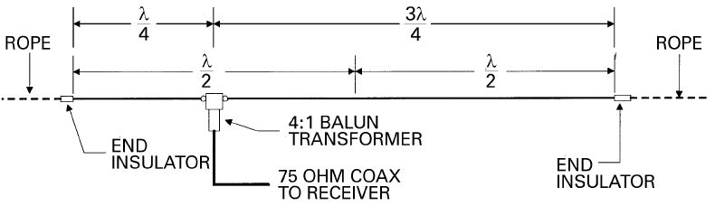
Holding true to the original Windom formulas, I used a ratio of 37.8% for one side and 62.2% for the longest side after determining the half wave length at the lowest operating frequency…. This is the 200Ω point, hence the 4:1 balun. (50Ω to 200Ω) The antenna is very simple. As already mentioned it is fed at the 1/3 point. So for 80m and up, you have one leg that is 45 feet long, and another leg that is 90 feet long. Some tweaking may be needed, but mine was built within an inch or two of those measurements.
The 10 feet vertical radiator really does radiate, and offers vertical radiation to the existing horizontal radiation, and therefore adds to the low angle omnidirectional radiation. The line isolator stops the vertical radiator radiating all the way back to the shack. Ideal height for the feed point is around 30-35 feet.
This is the same design as the ‘Carolina Windom 80 Special’