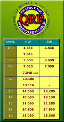
This circuit is for a QRP (low power) antenna tuner (transmatch) for use in the short wave amateur radio bands from 3-30 Mhz. It allows a wide variety of antennas to be connected to a low power transmitter. When the circuit is properly tuned, the maximum transmitter power will be delivered to the antenna. The tuner is normally is used in conjunction with a standing wave ratio (SWR) meter.
This is not the most versatile antenna tuner circuit, it will not match any possible load. This tuner is efficient and it is very simple to build and use. It is small enough for backpacking applications and is useful for matching many of the types of antennas that one might throw up on a camping trip.
Theory
The purpose of a transmatch is to match the impedance of a transmitter, typically 50 ohms, to an unknown antenna impedance. The circuit consists of a variable series inductor followed by a variable capacitor to ground. Most transmitter outputs consist of a PI low pass network. The transmatch is essentially an adjustable extension of that network. With the parts shown, maximum power through the unit is approximately 50 watts.
Construction
The tuner was built in an aluminum project box. Various holes were drilled in the box for mounting all of the components. When laying out the parts, leave plenty of room around the sides of the components to prevent RF arcing. Be sure to keep both sides of the variable inductor insulated from the box, you may need to use insulated bushings (non-conductive washers) on the inductor's shaft. Use heavy hook-up wire to connect the various components together, I recommend 18 gauge tinned cooper wire, or thicker. Use the shortest wire lengths possible. I used a fairly small box for the components that I had, a larger box would make the project somewhat easier to build.
Use
Connect the transmitter output to an SWR meter, connect the SWR meter output to the input of the antenna tuner, and connect the antenna to the output of the tuner. Antennas with a coaxial feedline should be connected to the BNC output connector. Random wire antennas should be connected to the banana jacks. The transmitter should be connected to a good earth ground at its chassis, the ground can also be connected to the lower (black) banana jack on the tuner.
With coax-fed antennas, the best location for an antenna tuner is where the coax feeds the antenna. Logistically, this may cause the tuner to be in a location that is difficult or impossible for the operator to tune so most people locate the tuner on the transmitter side of the coax.
Set the capacitance switch to 0 (center), adjust the variable capacitor to the mid point. Adjust the inductor to near the minimum inductance. Briefly transmit a CW carrier and observe the SWR reading. If your transmitter has an adjustable output power level, start the adjustment with low power then increase the power and fine-tune when a good match has been found.
Increase the inductance until the minimum reflected power and maximum forward power is observed. Adjust the capacitance for the best SWR reading. It is necessary to go back and forth on the adjustments to find the best match. If the best match is found with the capacitor at the max value, switch in either the 270pf or 510 pf parallel capacitors and re-adjust the variable capacitor and inductor.
Be careful not to leave the transmitter on for too long in the unmatched condition, doing so can damage the transmitter's output transistors. If your transmitter has a variable output power, tune up at low power then re-adjust the circuit at full power. Tube-based transmitters are generally more able to handle large output mis-matches.
Caution: higher power transmitters can generate high voltages within this circuit, don't touch any of the wires when the transmitter is operating. If the roller inductor's adjustment shaft is connected to the inductor's wiring, the shaft should be mounted so that it does not come in contact with the metal box. The set screw on the inductor's knob may be electrically hot during use, you may want to cover it with a drop of plastic glue or silicone after tightening.
Parts
variable inductor (roller), approximately 0-50 uH variable capacitor, 0-300pf or 0-360pf, can be scavanged from an old tube radio center off spdt switch 270pf, 200V silver mica capacitor 510pf, 200V silver mica capacitor two BNC connectors (or PL-259, the connector that won WWII, if you prefer) two banana jacks two insulated plastic knobs miscellaneous screws, nuts, and washers solid hook-up wire, 18 gauge or similar aluminum box, big enough to easily contain all of the components
The variable inductor may be difficult to find, the best places to look are at ham radio swap fests and surplus electronics parts companies. A fixed inductor with switched taps can be substituted. An air-core formed inductor will probably give the best results in this circuit, a toroidal ferrite core inductor will also work, but it may absorb some of the available RF power.