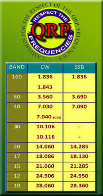
FOR USE WITH HALF WAVE ENDFED WIRES, 10 THRU 80 METERS
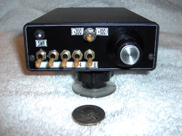
Since I got my Icom 703, I wanted a tuner to handle the 10 watts the 703 was capable of, and was designed to tune half wave endfed wires which is one of my favorite field antennas. I also wanted it to cover at least 10 thru 80 meters, thus the Switched Inductor L Match Tuner was born.
The Switched Inductor L Match is not my design, but is derived from a design from Steve Weber, KD1JV called the "ALT or Altoids L Tuner" and what I had in my junk box. Thanks Steve ! Steve used removable jumpers in the ALT to switch the various inductors in and out of his circuit, but with me being so "fat fingered", and likely to loose the tiny jumpers, I decided to simply use 5 SPDT mini toggle switches that are mounted on the front panel. To loose these, I'd have to loose the whole tuner and besides, I had the switches in my junkbox ! The switched inductor arrangement used in this tuner is capable of .5 uH increments from zero to 15.5 uH making it a fairly versatile arrangement. With this little tuner, I can tune halfwave endfed wires from 3.5 to 29 mhz down to at least a 1.5:1 swr or better, and it will handle at least 25 watts which is more than I ever intend on putting into it !
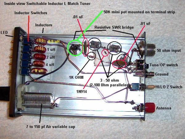
HERE'S AN INTERNAL SHOT OF THE TUNER SHOWING PARTS LAYOUT
Looking at this photo, you can see the 5 individual toroidal inductors and inductor switches (left side of photo). The inductors are in values of 0.5 uH, 1uH, 2 uH, 4 uH, and 8 uH. So each successive inductor is twice the value of the one before it allowing you to change inductance one half uH at a time which is a fairly precise way of doing it. A sixth inductor of 16 uH and another switch could be added for a total of 31.5 uH which would allow operation on 160 meters too if needed. But since I will only be using this tuner in the field and do not operate 160 from the field, I opted to leave it at 5 inductors. Also in the photo, you can see the variable capacitor, the resistive swr bridge, the hi / lo Z switch for reversing the the circuit for lower Z loads (will need much more capcitance for this by the way but its there if I need it), the antenna and ground connections, and the tune/operate switch for the swr bridge. I haven't added the switch in this photo for adding extra capacitance in parallel with the variable cap, but all it is, is a SPDT center off toggle switch that selects either a 100pf or 200pf fixed value caps to give up to a total of 350pf if needed. In the resistive swr bridge, the 3 50 ohm resistors (refer to schematic below) consist of 2 one watt 100 ohm metal oxide resistors in parallel each. Paralleling the resistors in this way allow the bridge to handle more power during tuneup, by I would suggest to use just enough power to get the LED to illuminate enough to give good indication. The 50K pot in the circuit is there to set the bridge sensitivity. Most resistive bridges use a little transformer here to boost the voltage to the LED when using really low powered rigs about 2 watts or less. But since I plan on using this tuner with my Icom 703 that does 10 watts out, I figured I didn't need the extra boost ! But I do turn the power down on the 703 when tuning up to save from interfering with others on the band and to help prevent overheating the PA in the radio.
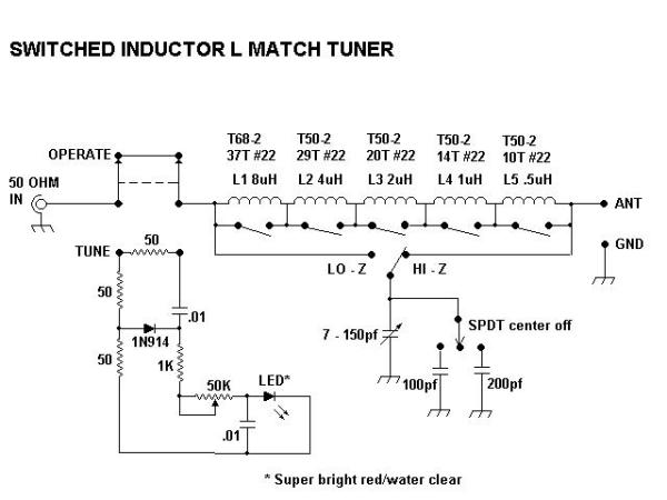
SCHEMATIC FOR THE SWITCHED INDUCTOR L MATCH
As you can see in the schematic, this is a standard L match circuit consisting of a series L shunt C which is very effective at taming the hi Z loads produced by endfed halfwave wires down to 50 ohms that your transmitter likes. With this circuit, you will be able to head out into the field with a multiband rig, some wire, and a power source and operate from almost anywhere. To figure the halfwave length of wires to use with this tuner, simply use the old standby formula of 468 / Freq (mhz) = Length in feet. NOTE: The tuner should work fine for wires that are multiples of half wavelength too !